
Cruise Control
Diagram of actuator mounted to gas pedal
Linear Actuator with IR sensor mounted on top
We have a linear actuator attached to the gas pedal. There is a magnetic hall sensor with a magnet mounted on the sprocket. We measure the time the magnet takes to go all the way around and then calculate MPH based on that value. There is a control system in the code to keep the actuator/ gas pedal at the point of 5MPH.
Actuator Specs:
-
100mm Stroke
-
10mm/s speed
-
IP54 Waterproof Rating
-
12VDC
-
Full Load is 20kg
Magnetic Sensor Specs:
-
Magnetic Hall Sensor
-
Sensing Distance - 10mm
-
Supply Voltage: 5-30VDC
-
Output State - Normally Open
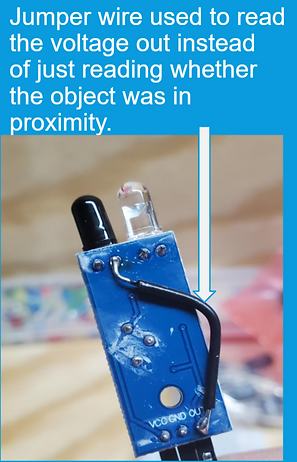
IR Sensor Specs:
-
Originally used as a proximity sensor. A jumper wire was used to get a voltage value off of the IR receiver pin.
-
Runs on 5v
-
Used in the control system to have a value for how far away the gas pedal is.

Magnetic Sensor


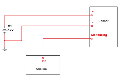
Multisim Wiring Diagram of the Linear Actuator


Speed sensor wiring diagram

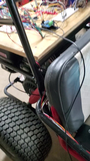
How the actuator was mounted
IR sensor wiring diagram
IR Sensor


My New Channel
Simple code to cruise at 5mph
Simple cruise code:
if(mph < targetspeed-errorband){
analogWrite(3, 0);
analogWrite(4, 70);
Serial.println("Too slow");
}
else if(mph > targetspeed+errorband){
analogWrite(3, 70);
analogWrite(4, 0);
Serial.println("Too Fast");
}
else{
analogWrite(3, 0);
analogWrite(4, 0);
Serial.println("In range");
}
}
This shows how the go-kart can hold a speed of 5mph with a PID-PI control system implemented
PID-PI Code:
float error;
float error1 = 0;
float PWM;
float sum = 0;
int K = 150;
int Ki = 100;//400;
float count=0;
float mph;
int oldtime=0;
int deltaT = 0;
float desired;
float Kp = 10;
float error_v = 0;
float count_600 = 0;
float offset = 0;
float error_v1 = 0;
float Kd = 1;
float sum2 = 0;
void isr()//interrupt service routine, used to do something without interrupting the main loop. Should be very simple instructions inside this function as to not hold up the main loop.
{
count++; //increasing revolution number
}
void setup(){
Serial.begin(9600);
pinMode (2,INPUT_PULLUP);
attachInterrupt(digitalPinToInterrupt(2),isr,RISING); //attaching the interrupt, used FALLING because my sensor is normally high and pulled low when activated
oldtime = millis();
}
void loop() {
// read the input on analog pin 0:
int sensorValue = analogRead(A0);
// Convert the analog reading (which goes from 0 - 1023) to a voltage (0 - 5V):
float voltage = sensorValue * (5.0 / 1023.0);
// print out the value you read:
Serial.print(voltage);
Serial.print(", ");
if( error_v >= 4 )
{
PWM = 255;
offset = voltage;
}
else if( error_v <= -4 )
{
PWM = -255;
offset = voltage;
}
else if ( abs(error_v) >= 1 )
{
sum2 = error_v + sum2;
desired = 0.01* error_v + 1*(error_v - error_v1) + 0.01*sum2 + offset;
error = desired - voltage;
sum = error + error1;
PWM = K*(error) + Ki*sum;
}
else
{
PWM = 0;
}
if(PWM>255){
PWM = 255;
}
if(PWM < -255){
PWM = -255;
}
//Serial.println(PWM);
if(PWM<0){
PWM = -PWM;
analogWrite(7,PWM);
analogWrite(8,0);
}
else{
analogWrite(7,0);
analogWrite(8,PWM);
}
error1 = error;
count_600++;
if(count_600 >2 ){
error_v = 5 - count;
error_v1 = error_v;
count_600 = 0;
count = 0;
}
Serial.println(error_v);
delay(100);
}